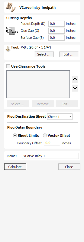
VCarve Inlay Toolpath
VCarve Inlay toolpaths allow easy generation of the Pocket and Plug toolpaths to cut out your design in 2 Parts ready for creating a VCarve Inlay piece.
Once the toolpaths are generated, they will create 2 seperate toolpath sets, one for the Plug and another for the Inlay itself.
Both of these have their own slightly different Tool forms when editing them after an initial Calculation.
Separate Toolpaths
After the original Calculation of your VCarve Inlay toolpaths, for the Inlay and Plug parts, they are no longer linked. If you Edit one of these, you need to ensure you make any suitable adjustments to the other sides toolpaths to match your changes. If you are unsure about this, consider deleting both parts of the Inlay toolpath and return to the original form to create a new set of VCarve Inlay toolpaths which take your desired adjustment into account from the beginning.
VCarve Inlay Toolpath - Pocket
Changing VBit
Both Pocket and Plug must use the same VBit to fit together correctly. If you need to change the VBit used in an VCarve Inlay toolpath, delete the Pocket and Plug toolpaths and regenerate a new VCarve Inlay toolpath with the appropriate new tools.
Watch this video to see this in action:
 Cutting Depths
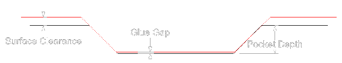
Pocket Depth
This is the Maximum Depth your Pocket will be cut down to, but may not reach this depth depending on the vector design and the angle of the VBit used.
Glue Gap
This is the distance between the Top of the Plug and the Bottom of the Pocket when the 2 halves are placed together.
This value should be greater than 0 and less than the Pocket Depth.
0.001"~0.01" or 0.02~0.2mm are common values to use but can vary depending on your project.
Surface Clearance
This impacts the gap between the lowest point of the Plug and the highest point of the Pocket Material piece.
The Higher the Gap value the less material is left on the Plug to remove later.
The Smaller the Gap value, the closer the two material pieces will be and the more sturdy the Plug Piece will be.
A value larger the 0.0 and lower then the material thickness must be used.
Tool
Clicking the button opens the Tool Database from which the required VBit Tool can be selected. See the section on the Tool Database for more information on this.
Clicking the button opens the Edit Tool form which allows the cutting parameters for the selected tool to be modified, without changing the master information in the database.
Use Clearance Tools
Check ✓ this option if you wish to use End Mill, Ball Nose or Engraving cutters to machine the large open regions of a design. If no tool is selected here but Flat Depth is specified then the selected V-Bit tool will be used to clear the flat areas as well as for the V-Inlay. All the tools in this section will leave an allowance for the V-Bit tool. Subject to this, the first tool in the list will remove as much material as it can, whereas subsequent tools will only machine areas the previous tools could not fit. The order of the tools in the list should match the order they will be run on the machine.
Clicking the button opens the Tool Database from which the required clearance tool can be selected and added to the list.
Clicking the button will remove the selected tool from the list.
Clicking the button opens the Edit Tool form which allows the cutting parameters for the selected tool to be modified, without changing the master information in the database.
Clicking the up and down arrow buttons will move the selected tool up and down the list respectively.
Plug Destination Sheet
This allows you to select the Sheet the Plugs Vectors and toolpaths will be placed on.
If the same sheet as the original vector is selected then the Vectors and toolpaths will be placed mirrored from the original vectors position.
If a different sheet is selected then the new vectors and toolpaths will be mirrored and moved to the center of the new sheet.
If the final position of the new generated vectors needs to be adjusted, move the vectors as normal and recalculate all toolpaths to update the toolpaths to match.
Plug Outer Boundary
Sheet Limits
This will create a toolpath to cut from the edge of the design to the sheet edge.
Vector Offset
With the Vector Offset option selected the Plug will only cut the area around the vector, which can help reduce the amount of material that needs to be cut, but this might require additional processing to remove the Plug from the surrounding material before it can fit into the Pocket part.
Boundary Offset
Increasing the Boundary Offset will increase the material removed around the Plug.
Negative values will be ignored, you will only be able to use a positive values in this field.
Name
The name of the toolpath can be entered or the default name can be used.